| Brief description and scope |
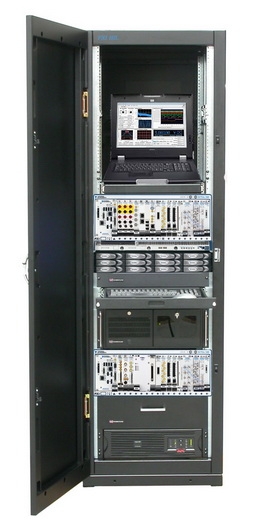
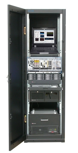
In this configuration, the multifunctional system PXI-HIL-Research & Development is designed to carry out research, development, experimental work in the following main areas:
- Studies of thin films and crystals
- Photovoltaics
- Studies of the characteristics of inorganic and organic phosphors
- Research of pn junctions and ohmic contacts of semiconductor structures
- Studies of the characteristics of electronic components
- Research of microelectromechanical systems
- Research of IC functioning
- Research of analog electronics components, semiconductor structures
- Studies of the operation of electronics modules
- Graphene
- Building an automated complex to create a multi-functional analytical laboratory
- Research of microelectromechanical systems
- Research in IMS (varying degrees of integration)
- Research of analog electronics components, semiconductor structures
- Research in the field of electronics micromodules
|
| Main Specifications equipment |
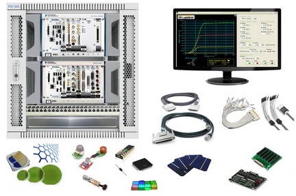
1 th logic module (two sets with hardware synchronization and extended frequency):
- PXI format controller, Intel Core i5-2510E dual-core central processor with a base frequency of at least 2.5 GHz and a frequency of at least 3.1 GHz in single-core turbo mode, 2 GB DDR3 RAM (expandable up to 8 GB), 1333 MHz;
- data bus bandwidth PXI 132 MB / s;
- 7 chassis module I / O signals, industrial chassis format "Euromechanics" to accommodate the embedded controller and 7 IO modules in the PXI format signals;
- 8 slot PXI 3U height;
- PCI bus with a data rate up to 132 MB / s;
- module synchronization buses;
- boundary 26,6 GHz;
- 32 analog channels with common or 16 differential;
- multiplexed analog channels polling mode;
- 625 ADC sampling frequency in kHz signal measurement mode, from a single channel, and at least 500 kHz signal measurement mode, multiple channels;
- ADC resolution 18 bit;
- Input signal range: ± 100 10 mV to ± V;
- Number of output analog channels 4;
- DAC sampling rate in MHz 2.8 lasing mode signals from one channel, 2 MHz lasing mode signals from the two channels, at least 1.54 MHz mode signal generation with three channels and at least 1.25 MHz mode signal generation with four channels;
- DAC resolution 16 bit;
- Output signal range: from ± 1 V to ± 10 V;
- 48 lines of digital I / O TTL (one 32 hardware clocked at up to 10 MHz);
- 2 counter / timer, with the characteristics MHz 80, 32 bit;
- software drivers DAQmx;
- ADC sampling frequency 1.8 MHz;
- input bandwidth 300 kHz;
- ADC resolution: up to 23 bits at the polling frequency of 1 Hz, and up to 10 bits at the polling frequency of 1.8 MHz;
- 20 function measurement signal parameters in the frequency and time domain;
- voltage registration - from ± 100 mV (with a resolution of 100 nV) to ± 300 V (with a resolution of 1 mV);
- current registration - from ± 20 mA (with a resolution of 10 nA) to ± 1 A (with a resolution of 1 μA);
- registration of resistance - from 100 Ohm (with a resolution of 100 μOhm) to 100 MOhm (with a resolution of 100 Ohm);
- capacitance measurement - from 300 pF (with a resolution of 0.05 pF) to 10 mF (with a resolution of 1 μF);
- measurement of inductance - from 10 μH (with a resolution of 1 nH) to 5 H (with a resolution of 1 mH);
- frequency measurements from 1 Hz to 500 kHz;
- collecting signals of currents and voltages with a sampling frequency of up to 1.8 MHz;
- 2 channel output;
Channel 0 (service) - Programmable power supply:
- Work in I and III quadrants in current or voltage source modes;
- The range of output voltages of up to 0 6 + B;
- Output current range from 0 to 1 A;
- DAC resolution 16 bit;
- Resolution of the ADC in the measuring circuit feedback 16 bits;
- Bare;
Channel 1 - source-Meter:
- Work in I, II, III and IV quadrants in the modes of a current or voltage source;
- Output voltage range ± 6 V and ± 20 V;
- Output current range from ± 200 μA to ± 2 A (5 subranges);
- DAC resolution 18 bit;
- Resolution of the ADC in the measuring circuit feedback 18 bits;
- Isolated;
- Total 8 W output power (W 46 with external power supply);
- 3 kHz refresh rate;
- The possibility of parallel and serial connection of channels to generate large currents and voltages;
- DCPower software drivers;
- 2 input synchronous channel :;
- ADC sampling rate in real time 100 MHz / channel
- ADC sampling rate in stroboscope mode 2 GHz / channel
- The input bandwidth 100 MHz;
- ADC resolution 14 bit;
- The input range of the analyzed signal is from ± 100 mV to ± 10 V;
- Input impedance 50 Ohm, 1 MOhm;
- Built-in Memory 256 MB / channel;
Scope driver software;
- 160 discrete input / output channels
- TTL logic level;
- Hardware clock of 40 MHz channels;
- The stability of the reference oscillator clock 100 ppm;
- I / O control: hardware and software based on FPGA;
- FPGA Xilinx Virtex II (3 million logic gates.);
- Support for the mode of data exchange via DMA channels;
- Built-in Memory 192 kB;
- The ability to implement proprietary data exchange protocols, specialized startup schemes, counters / timers, etc. based on FPGAs with a time resolution of 25 ns.
- RIO software drivers;
- 1 output channel;
- DAC sampling rate 200 MHz (400 MHz with hardware interpolation);
- DAC resolution 16 bit;
- Output range of the generated signal: from ± 2.82 mV to ± 6 V at a load of 50 ohms;
- Output Impedance: Ohm 50, 75 ohms;
- Modes of operation: arbitrary waveform generation, the generation of the standard types of signals sine, square, triangle, saw, noise;
- Band frequency outputs 80 MHz;
- Built-in memory per channel 256 MB;
- Digital LVDS connector for synchronous generation of digital signal representation;
- Size: no more than a 1 slot in a PXI chassis with a height of 3U;
- FGEN software drivers;
- The ability to synchronize via GPS, IEEE 1588-2008 (IEC 61588: 2009), or IRIG-B;
- Built-in high-stability TCXO 10 MHz (1 ppm);
- Integrated routing of internal and external clock and trigger signals;
- Support for the active GPS;
- Digital and analog triggers;
- Possibility of external clock;
2th logical module:
- PXI format controller, dual-core Intel Core i5-4400E central processor with a base frequency of 2.7 GHz and a frequency of at least 3.3 GHz in single-core turbo mode, 4 GB DDR3 RAM (expandable up to 8 GB), 1600 MHz;
- 1 GB / s PXIe data bus bandwidth;
- 2 Gigabit Ethernet port, 2 port USB 3.0, 4 USB 2.0, 1 port ExpressCard;
- chassis on 7 signal input / output modules, industrial enclosure format "Euromechanics" to accommodate the embedded controller and 7 input / output modules in PXIe format;
- 4 PXI slots, 1 PXI slot for timing modules, 2 PXIe / PXI hybrid slots, 3U;
- PXIe bus with data rate up to 3.132 GB / sec;
- module synchronization bus.
- The size of the hard 6 TB SATA II;
- Support regimes RAID-0 and JBOD;
- Write / read speed in RAID-0 mode 750 MB / sec;
- 32 digital I / O channels;
- Supports logical signal levels - 1.2 B, 1.5 B, 1.8 B, 2.5 B, 3.3 B, TTL, LVTTL;
- Ability to set different logic levels for input and output channels;
- Clocking channels - hardware with a frequency of 200 MHz;
- Built-in Memory 64 MB / channel;
- HSDIO software drivers;
- The number of input channels 2;
- The sampling rate of ADC 100 MHz / channel;
- The input bandwidth 100 MHz;
- ADC resolution 14 bit;
- Input range of the analyzed signal: from ± 100 mV to ± 10 V;
- Input impedance 50 Ohm, 1 MOhm;
- Integrated chip digital transfer frequency down signal (DDC) in the band up to 40 MHz;
- Built-in Memory 256 MB;
- Scope driver software;
- 1 number of output channels;
- DAC sampling rate 100 MHz (400 MHz with hardware interpolation);
- DAC resolution 16 bit;
- The output range of the generated signal is from ± 2.82 mV to ± 6 V at a load of 50 ohms;
- Output impedance ohm 50, 75 ohms;
- Modes of operation: generating arbitrary waveform and intermediate frequency signals for RF applications, the generation of the standard types of signals sine, square, triangle, saw, noise;
- Band frequency outputs 43 MHz;
- Low-voltage multiplexer / matrix switch - 48x1 (1-wire), 24x1 (2-wire), 12x1 (4-wire), 2 12x1 group (2-wire), 4 group 6x1 (2-wire) and 4x6 (2-wire );
- switching voltage: 60 VDC, 30 V (cc) alternating current;
- Maximum switched current: up to 1 A;
- Maximum current is passed: to 1 A;
- Maximum switching power: up to 30 W;
- Bandwidth: 10 MHz;
- Internal resistance (path resistance): 1 Ohm;
- Channel switching frequency: 200 Hz;
- Compatibility with software driver Switch.
|
| Software |
- Includes software for LabVIEW software and hardware simulation and testing in real-time;
- A graphical development environment that allows you to manage, synchronize and exchange data with hardware data collection, containing mathematical libraries that enable complex analysis of measured data, including time, amplitude, spectral, correlation, order, statistical and other types of single and multichannel analysis Analog and digital signals, containing examples for developing their own programs. The development environment should contain the editor of the graphical instrument interfaces with a set of ready-made controls and displays (buttons, switches, 2-x and 3-dimensional charts, etc.). The development environment should allow for the development of programs that interact over an Ethernet network through TCP / IP and UDP. The ability to present data by the user in digital, graphical, printed form and publication of reports in databases and the Internet.
- The professional version includes a completely ready-to-work environment with the following features:
- Distribution in the form executable applications, install packages and DLL;
- Integration with source code control systems;
- Manage and merge different versions of graphic source code files in one project;
- Tools of analysis and profiling of code;
- Specialized software for signal processing should include a full ready-to-use environment with opportunities:
- Wavelet analysis and application of digital filter units for registering short-term signals, eliminating noise and removing a trend;
- Frequency-time analysis, analytical and graphical tools for analyzing signals with a changing spectrum: quadratic algorithms, Gabor transform functions and dynamic filtering;
- Statistical signal analysis: multivariate statistical algorithms, modal analysis, algorithms for spectral estimation of random signals;
- Specialized software for configuring and running simulators and HIL-based systems PXI platform in real time.
- The software package should allow configuring the operation of signal input / output modules, FPGA-based modules included in the PXI simulation system, connect the module outputs to the hardware inputs of the data acquisition modules, and visualize the model output data.
- The package can also import a profile with the test modes, save and play back data from multiple .log files and create a user interface with the ability to change settings on the fly.
- The software package for graphical development of measurement applications and control in real time, must include a fully ready-to-use environment with opportunities:
- Applications for the creation of embedded and distributed systems;
- Integrated functions PID-controllers, control based on fuzzy logic;
- The ability to download to the target platform;
- time deterministic performance of code running real-time
- The software package for the development of algorithms on the FPGA in graphical form, includes a fully ready to work environment with the capabilities of:
- Do not you want to design the circuit board in the implementation of algorithms on reconfigurable I / O platforms;
- Frequency of loop execution to 40 MHz;
- Deterministic and simultaneous processing of signals;
- Ability to integrate VHDL code.
- The software package for the creation of models of management with the help of transfer functions or phase space includes a fully operational environment with opportunities:
- Building management models using transfer functions or the phase state space;
- Analysis Tools system performance - a step by step response, Bode diagrams;
- The introduction of a dynamic system on a real-time platform.
- Software package for the development of applications using state diagrams, a fully ready-to-use environment with opportunities:
- Simultaneous use of streaming data and description of the behavior of the application;
- Interactive debugging phase diagram;
- Coding for the PC, real-time systems, FPGAs, embedded systems and PDAs:
- Creating mixed tests for the study of materials and components.
|