

Introduction
The global industry produces more than 2,5 billion electronic products and devices per year. These are phones and smartphones, car controllers, printers, computers, etc. The basis of all these devices is a printed circuit board. On its surface and in the inner layers there are numerous printed conductors and electronic components (microchips, diodes, transistors, resistors, etc.). The more complex the electronic device, the higher the likelihood of a defect in its manufacture and installation of components. Eliminating defects (at work or, even worse, at the consumer) is a time consuming and costly process. The accumulation of visible and potential defects in production can lead to endless complaints and completely immerse the company in the process of eliminating defects. Automated high-speed testing of the printed circuit board at all stages of production allows for the timely localization of defects and rejection of products. The main types of testing electronic devices are automatic visual testing and functional testing. Visual testing allows you to detect defects in the installation of components using technical vision systems, and in-circuit and functional testing determine the static and dynamic characteristics of the device, their compliance with the required parameters.
The problem or task
To demonstrate the test system capabilities necessary to develop a test system that combines automatic visual testing and functional testing of the PCB.
Solution
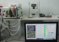
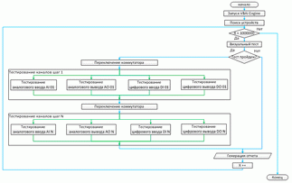
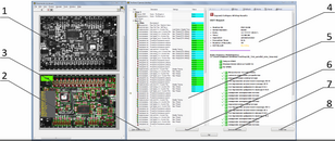
A system was developed for testing the PCB. As a test sample, the NI 6009 data acquisition and generation board was used. The system automatically performs visual testing for counting electronic components on a printed circuit board and testing I / O channels. To check the input channels, they were given a signal of a given value, which was compared with the signal value obtained after digitizing with a test board. To test the output channels, the test board generated a signal of a given magnitude, which was then compared with the signal value read from the board’s output channel by the test system. With the help of the matrix switch, all channels of the card under test were sequentially checked. The progress of the testing process is displayed on the screen, and after it is completed, the system generates a report that contains all the test parameters and their results. A test program that contains a sequence of individual tests (visual testing, testing of analog inputs, analog outputs) and the logic for the execution of this sequence was created in the NI TestStand environment. Tests were developed in the NI LabVIEW programming environment using drivers for working with the NI DAQmx data acquisition module and the NI SWITCH switch. For automatic visual testing, the NI Vision software module was used. The hardware system is built on the base of the PXI-1042 chassis with the 8108 controller. The chassis also included the PXI-6230 multifunction I / O module and the PXI-2531 matrix switcher (with the SCC-68 terminal block). The NI 1722 smart camera was used for the visual inspection. The control of the collection and generation of the test board signal was carried out using the USB interface. As a result of the work, a demo system was created, which checks the printed circuit board for the presence of all electronic components on it using automatic visual testing and verification of input / output systems.
Customer
is hidden
project Year
2011